
Design and Development
Some technical advances from 1875 to the present day,
and some things that stayed the same.
General
The breakdown cranes used on Britain’s railways changed little in fundamentals from first to last. They each consisted of a wheeled carriage upon which was mounted a revolving superstructure (or, traditionally, a “crab”) carrying a jib at one end and a counterbalance at the other. On the early cranes, the boiler, water tank and coal bunker alone could provide sufficient counterbalance whereas the later cranes carried a large mass of cast iron in the form of a tailweight. The jibs for the first 100 years of breakdown crane were all fixed in length, only the six which came into service in 1977 having telescopic jibs.
Centre Post
There were, of course, many technical advances over the years, a number of which have been discussed earlier in this document. Perhaps the most significant, in that it permitted large increases in lifting capacity, was the change from tall centre-post (or ‘kingpin’) to short centre-post. We’ll now look at the lead-up to this change and how it was implemented:
The first railway breakdown cranes (or “accident cranes” as they were called at the time) simply evolved from the design of contemporary manual cranes. This design included a tall centre-post with the vertical load of the superstructure carried on a bearing at the top and the horizontal loads carried at the top and bottom. The practical limitation on this design is the height and strength of the centre-post, which is subject to a very considerable bending moment.
The first evolution to allow greater capacity without breaking the centre-post was the addition of a pair of rollers to the front of the superstructure, but even so the maximum capacity achievable with the loaded centre-post design was reached with the 30-ton crane built by Cowans Sheldon for the L&YR in 1906 and the three 25-ton Cravens cranes built for the NER in 1907.
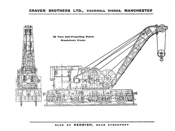
Craven Bros publicity document showing their 25-ton breakdown crane
The technological breakthrough that enabled the development of larger cranes was the adoption of the live-roller slewing ring by means of which virtually all bending forces are removed from the centre-pin. In this newer design, the slewing ring provides a significant path for load transference through the carriage to the rails, and to the extending girders if deployed, thus short-circuiting the centre-pin.
Not only are bending forces on the short centre-pin eliminated under practically all conditions of hoist, when the crane is working ‘FOR’ (Free on Rail, i.e. light lifting without the girders extended) neither will there be any significant tensile loading on it. The pin’s primary function when lifting FOR is to keep the roller paths in alignment since the downforce through the combined centre of gravity of the superstructure and load will fall within the diameter of the roller path (the roller path being generally wider than the track gauge, or more precisely the rail head centres, within which the centre of gravity must fall if the crane is to remain upright when operating FOR).
Tailweight
In order to remain stable when lifting, the combined centre of mass of the crane and its load must fall within the “footprint” of the crane, the width of the footprint being defined by the wheels when operating free-on-rail (FOR) and by the propping girders when operating propped and clipped (P&C). To balance the load on the crane hook, clearly a tailweight is required, and since the tailweight is generally nearer to the centre-pin of the crane than the load, the mass of the tailweight may need to be considerably greater than the load to be lifted when operating FOR.
Many early hand cranes had a ballast box at the rear of the crab which was on rollers and could be rolled rearwards to counterbalance the load being lifted (most early hand cranes did not have propping girders and hence stability had to be regulated quite precisely). As steam cranes became dominant, initially no movable or removable tailweights were provided, adequate stability being available due to the weight of the boiler, bunker and water tank to allow cranes of up to about 25 tons capacity to operate with comparative safety, however as 36-ton cranes became available it became necessary to increase the counterweight of the crane to a point where the axle loading of the cranes would have exceeded the track standards of the time. This first became a problem with the two 36-ton cranes ordered by the GWR in 1908 from Ransomes & Rapier and Stothert & Pitt, and the two makers adopted different solutions.
The 1908 Ransomes & Rapier crane, GWR No. 2, used a removable counterweight, a large casting of some 6½ tons, which was bolted underneath the rear of the superstructure when needed. When running in train formation this weight was carried in a support wagon together with the crane’s propping girders, thus minimising the axle-load of the crane. The second R & R 36-ton crane for the GWR, No. 3, was identical in design to No. 2, and when the first three 36-ton cranes for the LSWR were built to a derivative of the GWR design, the practice was continued, although the LSWR very quickly allowed the tailweights to remain in place when running in train formation, something the GWR never sanctioned (it is recorded that it took approximately half-an-hour to fit the tailweight to the GWR cranes on arrival at the work site).
The 1909 Stothert & Pitt crane which became GWR No. 1 had a counterweight that was both removable and movable. This was mounted underneath the rear of the superstructure (in addition to various fixed weights built there into) and could be cranked manually from a position close to the roller path (minimum counterbalance for light lifts) to a position at the extreme rear of the superstructure (maximum counterbalance for heavier lifts). The feature of a movable counterweight was unique to this design, and was not used on any British railway BDC thereafter until the telescopic jib 75-ton cranes of 1977.
The removable tailweight was satisfactory for cranes up to 36-tons or so capacity, but the complication of having to fit the weight and the practical limitation on the size of the weight meant that it was not suitable for larger cranes, and it was the invention of the Stokes Patent Relieving Bogie, described later, which enabled the construction of the 45-ton cranes. There were in fact two cranes of 45-tons capacity in this country without relieving bogies, the two LNER bogie cranes of 1926, and these were well-known for their high axle loads.
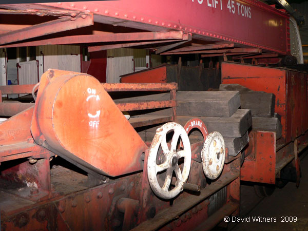
Two 45-ton cranes in action. ADRR95214 (nearest) was provided with weight relieving bogies (only the tail bogie can be seen here) whereas ADRC95224 has no relieving bogie provision. Both these cranes are preserved on the North Yorks Moors Railway.
The mass of the crane carriage will have some bearing on the stability of the crane when operating FOR but is unlikely to play a significant part in keeping the crane from overturning. Of greater impact is the divergence from equilibrium between the sums of the moments in front of and behind the centre pin. Forward stability with the jib over the side depends upon the difference between the sum of the moments of the jib, block, hook and load and the sum of the moments of the counterbalancing masses. Calculations for forward stability under various degrees of rail cant should presuppose a low water level in the boiler and an empty water tank and coal bunker, but calculations for rearward stability should include an assumption that the boiler, water tank and coal bunker are full and there is no load on the hook (in fact it is safer to assume no load per se since, in unusual but possible circumstances, the block and hook could be fully resting on the ground with the jib raised high).
Some of the larger cranes in particular can be tail heavy when the jib is raised to any great extent and there is then a risk of toppling (i.e. falling over backwards) with the jib to one side, especially on canted track, unless the girders are in use. Once a crane starts toppling there is little or nothing that can be done to retrieve the situation, whereas a forward overturning movement that is caught early enough may well be made safe by either quickly releasing the load or letting the crane go down until the ground relieves the load and then carefully easing off the hoist brake to let the crane carriage find its way back to where it should be. The latter procedure becomes more feasible if the load being lifted is maintained close to the ground and this is just one of the reasons why minimising the height of lift is always good practice, though some lifts such as those involved in bridgework or lifting loads over obstructions may entail loads being suspended unavoidably high above the ground.

Tail Heavy warning plate on Ransomes & Rapier 45-ton crane ADRR95214.
Super-elevated (canted) track is typically found at curves in the line but may occur
elsewhere due to unbalanced formation settlement.
Contrary to the situation with FOR operation, if the crane is engaged in heavy lifting with girders extended then the centre of gravity could be well outside the roller path and there will now be a force in the pin, effectively the force that stops the superstructure falling off the carriage, however this force will be mainly tensile and probably not enormous.
It was the successful adoption of the live roller slewing ring and short centre pin on the GWR No. 2 crane of 1908 which resulted in these features becoming the de facto standard for all subsequent crane designs.
Cast Iron v Cast Steel
Towards the end of the 19th century, cast iron started to be replaced by cast steel for stressed parts on breakdown cranes and it wasn’t long before the only notable part made in cast iron was the tailweight. Larger cast steel parts, such as the superstructure bedplate, might need to be cast in two or more parts and welded together. An example of this came to light when 1931 Ransomes & Rapier crane, LMS No. MP3, was stripped of paint and scale during its restoration in 2009; the bedplate was found to have been cast in three sections and subsequently welded.
At around the same time as the move to cast steel, chains for derricking and hoisting were phased out, to be replaced with steel wire ropes.
Motive Power
The power for breakdown crane operation was traditionally steam but, as will have been seen earlier in this document, there was a move to, firstly, diesel-mechanical (the four cranes for the Southern Region in 1962-64) and, later, diesel-hydraulic (the conversions from steam in 1976-78 and 1985-87, and the 1977 new-build telescopic jib cranes).
Weight-Relieving Bogies
As the 20th century was entered, breakdown cranes were becoming larger in lifting capacity to cope with heavier locomotives. Though the cranes had no hammer blow to damage the track, they were still restricted as to where they could travel due to their high axle loads, especially away from the main lines. For example, branch lines, sidings and bridges could present a difficulty.
In 1904, Ransomes & Rapier’s chairman and managing director Wilfrid S. Stokes invented weight-relieving bogies as an answer to the high axle-load problem. Stokes had been New Works Engineer for the GWR before moving to Ransomes & Rapier in 1896. He was, incidentally, knighted for his invention of the Stokes mortar in 1914, this becoming the standard British gun of the First World War.
Stokes’s weight-relieving bogies were two-axle (or in the case of some cranes built for export, three-axle) trucks, located one to the front and one to the rear of the crane carriage, onto which some of the weight of the crane could be transferred so as to reduce axle loadings for travel. As an example, a four-axle crane weighing 80 tons could be re-configured, together with its two weight-relieving bogies of, say, 10 tons tare apiece, to give a loading of 12.5 tons per axle on each of the eight axles of crane carriage and bogies.
At the work site, the transferred weight would be reinstated onto the crane before the lifting operation commenced and there was then an option to shunt the jib runner and bogies clear of the crane, or to lift them off the track altogether so as to give close access to the job in hand. Thus the relieving bogies not only helped with axle loadings, they also assisted in keeping the crane carriage to a compact length for working close to the load. Further benefits were articulation and a shorter jib runner.
Stokes protected his invention in the UK under patent number GB 12927, granted on 6th April 1905, but relieving bogies featured on only two cranes before the patent expired, a 20-ton crane for the Great Indian Peninsular Railway in 1906 and a 36-ton crane ordered by the Midland Railway on 22.4.1914 for their Derby depot.
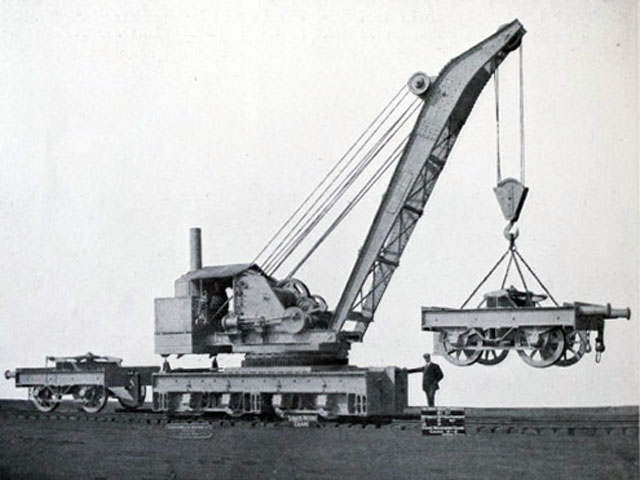
This 20-ton crane, supplied to the Great Indian Peninsular Railway in 1906, was the first crane to be built with relieving bogies. Weight transfer on/off bogie was by ratchet lever.
In 1930, Wilfrid Stokes's nephew Antony Scott Stokes was granted Patent No. GB 323723 to protect improvements he made to the relieving bogie system, these providing in particular for the bogies to pitch and roll in relation to the crane during haulage. The improvements were incorporated in Rapier's 36/40-ton crane built for the LMS in 1931 and 35-ton crane built for the LNER in 1932, and they subsequently appeared in the 45-ton cranes.
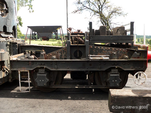
Tail end bogie for 1931 Ransomes & Rapier 40-ton crane MP3, with cover removed to show the wormgear drive. Note the uncomfortably high operating capstan.

Overhauled tri-point load bearing beam from the tail end bogie of MP3
None of the eight cranes of 35 or 36-ton capacity built by Ransomes & Rapier for GWR, LNWR, GER, L&SWR and SR between 1908 and 1926 had weight-relieving bogies. Instead they were five-axle cranes, two of the axles being in a bogie arrangement directly under the tail end of the carriage with the resulting overhang to the rear increasing the minimum working radius of the hook compared with the Stokes bogie cranes. No more cranes for use on Britain's railways were built with relieving bogies until 1931, however they became the norm thereafter for all railway breakdown cranes with a lifting capacity of greater than 30 tons.
The weight-relieving bogies could be problematical to re-engage with the crane carriage at the end of the lifting operation. This drawback together with the extra length of the crane in running order may have been behind the reluctance of railways other than the Midland and LMS,and the LNER until 1932, to buy the type (though the mounting and dismounting of the removable tailweight or ‘kentledge’ on the alternative five-axle cranes, one purpose of which was to reduce axle loading, would likely have been a comparable inconvenience).
For the six 45-ton ‘war emergency’ Stokes-bogie cranes built by Ransomes & Rapier in 1940, the load was transferred onto and off each bogie via a handwheel fitted at a lower height than the rather high four-spoke capstan of the 1914 and 1931 MR/LMS cranes. The handwheel was connected to the bogie loading mechanism via chain and sprockets, with a nominal 4:1 reduction for easier operation. The 1940 bogies were fitted with a handbrake, a feature sadly lacking on some earlier bogies which required wheel-chocking to prevent them running away when uncoupled!
Stokes's relieving bogie for 1943 Ransomes & Rapier 45-ton crane ADRR95214, showing the handwheel for transfering some of the weight of the crane onto and off the bogie
The bogie for ADRR95216, the 45-ton crane built in 1944 to replace Exmouth Junction’s Stothert & Pitt 20-tonner (which was unable to handle the Merchant Navy class of loco) was a substantial redesign, though still to the earlier principles. Notable was the hand-pumped hydraulic system for load transference from crane carriage to bogie, this system first being fitted to the Ransomes & Rapier 45-ton cranes provided to the Ministry of Supply.
Stokes's bogie, tail end, for 1944 Ransomes & Rapier 45-ton crane ADRR95216. Note the hand pump for hydraulic transfer of some of the weight of the crane onto the bogie.
Cowans Sheldon and Craven Brothers provided their own patented designs of relieving bogies for the 36-ton cranes which they supplied to the LMS in 1931, the LMS having ordered three cranes from Cowans Sheldon, two from Craven Brothers and one from Ransomes & Rapier, all to the same basic parameters. Externally, the relieving bogies from all three makers were of not too dissimilar appearance and all used the Stokes principle, however there were subtle differences in their construction and method of load transfer.
Extending from the Cowans Sheldon bogie was an arm which could be raised by the crane hook so as to load the bogie by the specified amount, a locking pin then being inserted. Release was by again raising the arm with the hook and withdrawing the pin. This method eliminated the need for crane carriage weight to be transferred on and off the bogie by manual effort, however later versions of the bogie were provided with a manually-operated hydraulic jack for transferring the load, the hook-raising arm being retained for emergency use.
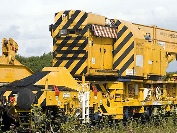
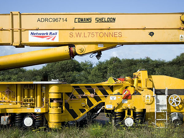
Eleven Cowans Sheldon cranes of the relieving bogie type were supplied to UK railways pre-nationalisation and a further nineteen in BR days, the final of which were the six 75-tonne diesel-hydraulic cranes built in 1977.
Loading was applied to the Craven bogie via a large handwheel which was similar in form to a ship’s wheel and was placed at a height convenient for turning by a man standing on the track formation. Turning the handwheel operated a horizontal screw jack connected to scissor arms beneath the top deck of the bogie, thus loading or unloading the bogie as required. A locking pin was inserted through a side panel once the correct loading level had been reached.
The only Craven cranes with weight-relieving bogies provided to UK railways were the two 36-ton breakdown cranes for the LMS in 1931, however the design was later taken up by continental crane builders.
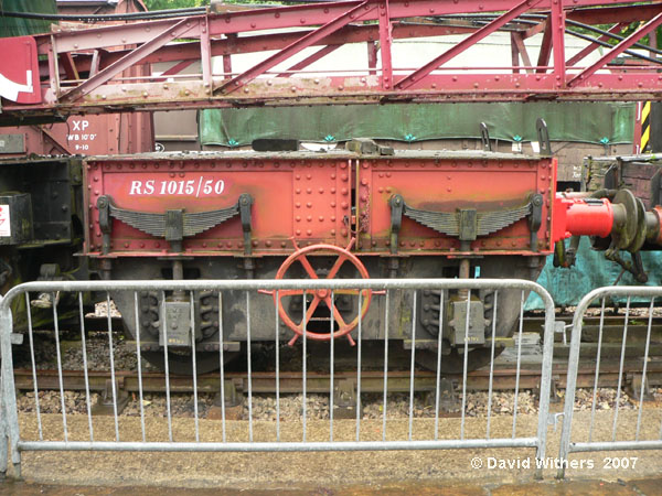
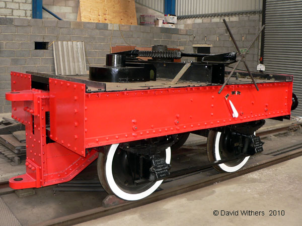
Jib end relieving bogie for 1931 Craven 50-ton crane ADRV95206
When the specifications were being drawn up for the six 75-ton extending-jib cranes built in 1977, full account was taken of the connecting problems of the earlier cranes. The bogies of these new cranes, and their coupling mechanism, were to a completely different design as described later under "New Design with Telescopic Jib".
Articulated Jib Foot
All strut jib breakdown cranes, other than the very earliest, required a jib runner to carry the front end of the jib. As well as serving to enable the crane to be coupled into a train, the jib runner carried a bolster with a roller arrangement upon which the jib rested, the bolster having side stops to limit the extent of sideways movement of the jib nose. The superstructure tail was semi-rigidly locked to the carriage via chains or a spring-loaded centering device. A problem with this system was that entering tight curves in the line could cause the jib nose to slew against the stops so fiercely that there was a danger of the sideways shock derailing the jib runner.
Craven Brothers, in their two 36/50-ton cranes built for the LMS in 1931, overcame the jib-slewing problem with the introduction of the ‘articulated jib foot’ which was to later become the norm for all strut jib breakdown cranes. By slotting the holes which receive the fulcrum pins at the foot of the jib, back and forth movement of the pins in their respective holes is permitted when the jib is near-horizontal and resting on the bolster. The result is that, during negotiation of curves in the line, the jib head follows the course of the jib runner whilst the superstructure remains in line with the carriage (to which it has been locked).
Rail Clips
From the very first days of the breakdown crane, a clip or anchor was provided at each of the four corners of the carriage to secure the crane to the rails in case of overloading and so help avoid overturning. One end of the clip was attached to the crane carriage and the other end was clipped onto the rail by means of a sliding collar. The two ends were connected by a screw-coupling for tightening and loosening.

Rail clip on 1931 Ransomes & Rapier 40-ton crane MP3/ADRR95207
There was no significant change in the design of the clips from those on the pioneer 5-ton Appleby Brothers cranes supplied to the Midland Railway in 1875 right through to, and including, those on the 75-ton Cowans Sheldon cranes supplied to British Rail in the 1960s.
Whilst the clips on a 5-ton crane could be relied upon to hold the crane upright at a time of instability, when the later, heavier, cranes became unstable the clips were likely to lift the track panel as the crane started to topple. It thus became the norm, with the heavier cranes, to leave the coupling slightly loose and have a man watch for it to tighten, whereupon a sharp warning to the crane driver should have him relieve the load and so keep the crane upright.
Some old hands would lodge the blade tip of a shovel between wheel and rail, any slight movement of the handle of the shovel giving early warning of wheel lift.
If the crane did lift its wheels on one side, the rail clips would generally hold the rail against the wheels and so help prevent the crane derailing as it settled back down, however the crane foreman could be expected to have some explaining to do as the track would likely be damaged.
In summary, whilst the basic design of the rail clips didn’t change during close to 100 years, the mode of operation was modified to suit the evolution of the British breakdown crane from 5-tons capacity through to 75-tons.
New Design with Telescopic Jib
One’s first impression of the telescopic jib breakdown crane may have been of dismay as it is far removed from the traditional strut jib crane that served the railways well for a century or more. But if we scrutinise the design we are in for a number of agreeable surprises...The introduction in 1977 of a completely new breakdown crane with telescopic jib saw an end to the 100-year evolution of the classic strut jib crane. That evolution had brought about many detail improvements but it hadn’t kept pace with the changes in railway operational needs, nor with advances made in mobile cranes generally.
What was needed at that time was some innovative thinking, learning from the past but not being led by it, and that is exactly what happened.
A British Railways Committee on breakdown work, set up under the chairmanship of Mr K R M Cameron, thoroughly analysed the railway’s breakdown and recovery equipment needs and its report of April 1970 recommended the provision of new high capacity cranes. The outcome was the building of six 75-tonne telescopic-jib cranes of an advanced design, these being the last breakdown cranes to be built for home railways.
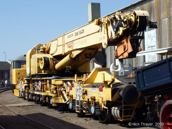
Tele-jib crane ADRC96710 at Eastleigh's Open Day in May 2009
A paper entitled “Design and Development of New 75 Tonne High Capacity Rail Cranes” (see Bibliography) gives an excellent account of the specifications, design and development of these new cranes. There follows here just a brief outline of some of their features and attributes:
An extensible jib is far more practicable than a strut jib for lifting under electrical wires. It also dispenses with the need for a jib runner and, in conjunction with a movable tail ballast, it enables balanced axle loads for travelling in a train. The majority of the earlier heavy breakdown cranes, in order to achieve some level of axle load balance, had their slewing ring offset towards the front to help counter the fixed mass of the tailweight. The telescopic jib cranes are symmetrical and can travel to the work site either way round as each end has the same outreach. This frees the crane foreman from having to ensure that the crane is ‘right way round’ before travelling to the job – or, worse, suffering the indignity of it being found ‘wrong way round’ upon arrival!
The tail ballast is hydraulically movable between two positions so as to keep the centre of gravity of the superstructure as close as possible to its centre of rotation. This ‘travelling ballast’, in conjunction with the telescopic jib, avoids the instability problem faced by the strut-jib/fixed-tailweight cranes, the 75-tonners in particular being susceptible to falling over when the jib is slewed to one side on canted track without the girders (outriggers) deployed. On these new cranes, the tail ballast is held in a forward position for both travelling and lifting ‘free on rail’ and in a rearward position in conjunction with outrigger deployment for lifting heavy loads.
The travelling tail ballast is mounted on tracks each side of the engine room
All breakdown cranes of greater than 30 tons capacity built for home railways since 1939 relied on weight-relieving bogies to keep axle loads within acceptable limits when travelling in a train and the new 1977 cranes continued this practice, spreading the weight of the four-axle crane over eight axles when in running condition. The various adaptations of bogie coupling on earlier cranes had suffered one thing in common, a severe reluctance to re-couple to the crane carriage on any other than straight and level track, and settlement of the springs could make it difficult even then. This problem strongly influenced the design of a new type of bogie coupling for the new cranes, as will be described:
The 1977 cranes each have four outriggers of the ‘swing’ type, this being a ‘first’ for a British breakdown crane. They are hinged to the crane carriage and, most ingeniously, they dual-role as bogie couplers. The outriggers are fitted one to each corner and can be moved hydraulically from a parked position adjacent to the crane carriage (for free-on-rail lifting alongside an obstruction such as a station platform) to any one of three crane-stabilising positions. In preparing to run the crane in a train, each end pair of outriggers is swung, hydraulically, away from the crane carriage until their outer ends meet each other at the centreline of the track. They are then locked in this position to act as bogie couplers. The crane is driven against each bogie in turn and is automatically coupled, the hydraulic outrigger jacks then being operated so as to provide a downforce on a lever mechanism on each bogie sufficient to load all eight axles evenly. The bogie connections are then locked in position and the outrigger jacks relieved of hydraulic pressure.
The new cranes were delivered in 1977 but were used only for training purposes and experience-gaining until powered outriggers were provided for them in 1980.
Tele-jib crane coupled to the jib-end relieving bogie via its front pair of outriggers
In the absence of a jib runner, another means had to be found for hook and block stowage on these new cranes. Stowing on a relieving bogie was not feasible since the leading end of the jib extends beyond the front of the leading bogie. It was decided to clip the block to the underside of the jib and a method was found to utilise the jib’s hoist and telescopic motions to put the block into its stowage position, a locking pin then being inserted to positively retain the block to the jib.
Powerpack options of diesel mechanical, diesel electric and diesel hydraulic were considered by the design team. It was decided that diesel mechanical would be unsuitable for telescopic jib operation, and diesel electric unsuitable in respect of load gauge, performance and telescopic jib requirements, so a diesel hydraulic power pack was developed. This enabled one common power source, a Rolls-Royce C6TFL diesel engine, to power all the main crane motions plus the travelling ballast, outriggers and other auxiliary requirements.
The power pack is mounted on a track on the superstructure and can be withdrawn as a unit for major maintenance, whilst lift-off doors give access for in-situ servicing. The travelling ballast is also on tracks and is in two halves, one to each side of the power unit.
The suspension needed to be soft for a comfortable ride and to control wheel unloading on twisted track when running, but firm for craning over the side. The necessary compromise was settled on, with the crane mounted on coil springs with hydraulic dampers.
Towards the end of the 1990s, the five telescopic jib cranes still in service (ADRC96711 having been withdrawn due to damage) were updated by Cowans Sheldon. The updates included an improved safe load indicator, a new Cummins diesel engine, an enhanced hydraulic system, six additional brake disks, improved slew ring bolts to overcome fatigue failures, better work area lighting and a new operator’s cab on anti-vibration mountings with a rear-facing video monitor and radio and public address systems.
 |
Updated 8th April 2012 | Back to top of page | Copyright Copyright BDCA 2010,2012. All Rights Reserved |